In this section we will look at the various ways that computational modules typically communicate with each other. We can subdivide a typical desktop hardware environment into two areas: internal communications (i.e. inside the case of the computer), and external to the case, which today is mainly USB and Firewire.
This is the type of communication we have been assuming in the discussions on register transfer in the previous page of these notes. Data is accepted by the receiver on the rising edge of the clock, and becomes visible to the next stage in the system a bit later due to the flip flop delay of the registers.
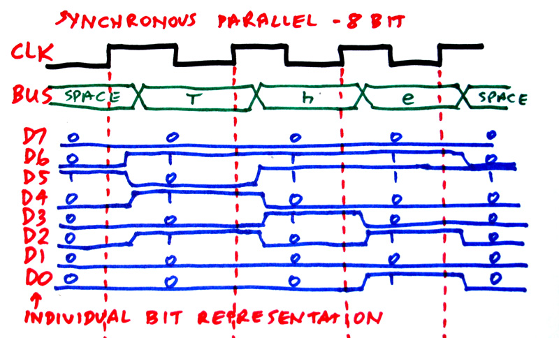
In the diagram below, we see 8 bit parallel data consisting of a character string. This diagram would be quite close to the actual protocol used in an early x86 machine running a rep movs instruction. [Modern x86 machines would move the data 8 bytes at a time over a parallel 64 bit bus whenever possible.]
We see that the data changes just after the rising edge of the clock. This is the usual situation in a fully synchronous system (every flip flop in the system being clocked by the same clock.)
I have shown both the bus representation of the data and the representation as individual bits. Normally, the bus representation is preferred due to its compactness, although control signals (LOADs, CLEARs, etc) will be shown individually.
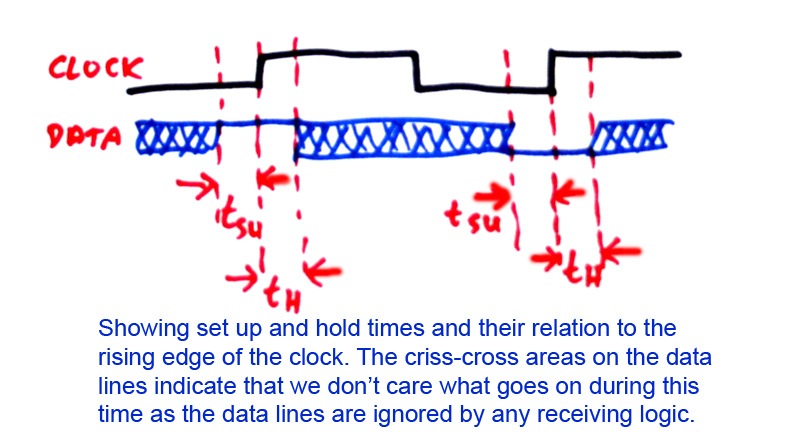
The timing diagram as shown above is rather wastful of time, since the data appear to be stable long before the next rising clock edge. For reliable operation, the data must be stable just before the rising edge ("set-up time") and remain stable for a short period just after the clock edge ("hold time"). Geerally, modern systems allow a hold time specification of 0 ns (nanoseconds) since internal delays in the receiving register will supply the necessary time.
This interface is used internally in the computer, and especially on the motherboard and inside the CPU chip itself.
Other internal parallel interfaces include PCI (Peripheral Component Interconnect), used for the expansion card slots on the main board of the computer, ATA (AT Attachment) also called IDE (Integrated Device Electronics or Intelligent Drive Electronics) for disk drives. Additional interfaces are used for memory connection-to be discussed on the system architecture page or lecture.
The problem with sync parallel is that it is difficult to impossible to maintain full sync over any sizeable distance; it may be impractical to broadcast a clock signal from a computer to a printer, for example. Different computers use different clock rates, and different printers use different clock rates for their embedded CPUs, so we would have compatibility issues even if we COULD transmit the clocks easily. Also another problem, TIMING SKEW, is an issue and will be discussed more fully later on this page.
So, we use a "handshake" method. The basic two-wire handshake scheme uses "STROBE" to tell the receiving device that data is available physically on the wires or cable, and "ACK" for acknowledge, which is sent by the receiver to the transmitter to tell the transmitter that the data has been accepted and the transmitter can now set up the next data.
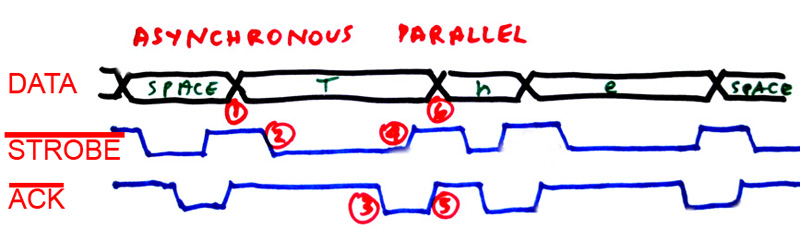
In the diagram above, we can trace the operation on transmission of the letter 'T'.
1. The letter T is written to the printer port. This is typically done by use of the OUT
	 instruction for the x86, as the LPT port is wired into the PORT system of the x86.
2. The falling edge of !STROBE is now sent. In this particular protocol, things are falling edge
	 activated.
3. Eventually the printer accepts the data from the cable, and replies with !ACK falling edge.
4. The port sees this falling edge, and resets !STROBE and in a typical application, creates an
	 IRQ which calls an interrupt service routine (ISR) which moves the next character to the port
	 (point 6).
5. The printer raises !ACK. The port will not send !STROBE until !ACK is high.
6. The port sends the next character.
I have drawn the diagram to show that the data rate is flexible. The printer is slow to accept the 'T' presumably because it is busy at the instant that the T is sent.
This type of protocol is very old, dating back to the 1950s. It assumes an unbuffered receiver-we have full handshake on every character. Cheaper systems often omitted the ACK signal, assuming that the receiver was always faster than the transmitter. As memory became cheaper, buffered receivers became common, so the protocol was modified to allow synchronous bursting, clocked by the !STROBE signal. The receiver would eventually reply with an equal burst of !ACK pulses, telling the transmitter that all bytes of the burst were successfully received. The simple protocol shown in the diagram is essentially the setup for basic SCSI-1, which allowed a maximum speed of 5 MB/sec. (SCSI = Small Computer System Interface). SCSI-2 incorporated synchronous bursting.
This interface is used for external data movement.
In serial transmission, the data is moved one bit at a time over a single wire.
The following diagram shows the timing for a simple serial transmitter. Here, parallel data is loaded into a shift register (diagram shown later) by the LOAD pulse (and, of course, the system clock). Data shifts out at the desired bit rate in the following order: start bit (0), data bits starting with least significant bit, then parity bit, if any, then stop bit (1). If another character is not immediately ready to tsend (for example, if a person is typing the characters and they are being sent as they are typed) then the line stays at 1 until the next character is ready. This sort of thing was first developed by the American military in the 1950s as part of the SAGE project, to allow communication from radar stations to central computers that would analyze radar data of possible attacking airplanes (presumably from Russia, carrying nuclear weapons).

Back in the 1970s regional reporters for magazines and newspapers could submit their copy using teletype machines over the phone lines. Because long distance phone line time was very expensive (like maybe $25 per minute in today's dollars to Toronto) the usual practice was to type in the story and store it on paper tape, then dial the number and start the paper tape, which would transmit at 10 characters per second. Since each character had start bit, 8 data bits, parity and stop bit, the bit rate was thus 110 bits per second.
The data are sent over the phone line as sound pulses or bursts. Rapid improvements in analog filter technology resulted in improvements in the bit rate. In 1978 I did some CPSC courses, working the labs from home at 300 bits per second using a CRT terminal (a "glass teletype") and also a printer. Through the 1980s the data rate crept up to 1200 bits/sec, 2400, 4800, 9600, 14400, 19200 and finally topping out at about 33000 bits/sec, which is about the maximum theoretically possible through an asynchronous analog phone connection. All this is now called POTS ("plain old telephone service"). It has been replaced with ADSL (asynchronous data subscriber line) over the phone lines, and cable, which uses effectively a TV station band (shared among several subscribers at any one time).
Note that the use of the start bit means that the sender and the receiver need not run at the exact same bit rate; in fact, a difference of about 5% is possible.
(Q) Explain how the start bit allows for a bit rate difference between receiver and transmitter for the asynchronous serial data transmission protocol. How much difference is possible?
(Q) Since it is easy today to maintain data bit rates consistent to 0.1%, we could send the data in larger blocks. How large could the blocks be before a synchronization bit, like the start bit, is needed? What improvement does this give in the effective data transmission rate?
The diagram below shows the basic parallel to serial converter. Since the computer internally moves data around using synchronous parallel method, we need to convert, using this hardware:
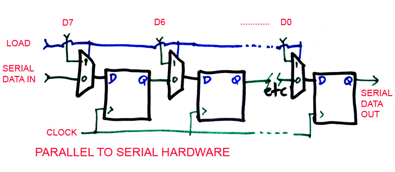
We see parallel data connected in from the top of the diagram to a series of 2x1 MUXes. If LOAD is 1, all the flip flops are simultaneously loaded with the parallel data D7, D6, ...., D0. Two additional flip flops can store the start and stop bits, being hardwired on their inputs to 0 and 1 respectively. If load is 0, successive clock pulses simply shift the data in the flip flops to the right, so that on each clock pulse, the next bit becomes visible on Q of the leftmost flip flop. The node SERIAL DATA IN can be simply hardwired to 0.
This hardware will actually convert serial to parallel also-it could be part of a receiver. The data from the receiving line could go into the SERIAL DATA IN pin. After the right number of bit clock pulses have occurred, all the Q's of the flip flops together will contain the received character.
This interface is used for very long distance external data movement.
Both the asynchronous serial and parallel interfaces are virtually obsolete on the desktop. Also, the ATA/IDE interface inside the computer for disk drives is fading away, and is being replaced with SATA (Serial ATA).
Comparing data rates, parallel ATA maxes out at 133 MB/sec or about 1066 M bit/sec. SATA rates are 1500 M bit/sec or 3000 M bit/sec, clearly faster (assuming no bottlenecks elsewhere, and assuming the drive spinning can physically supply data fast enough!) Both the serial and parallel data rates must be reduced by 10-20% to allow for framing, protocol and error-checking overhead.
It would seem clear that parallel interface will give the maximum speed, perhaps at the cost of more wires and pins. However, if the length of the cable is more than a few centimeters, this is no longer true.
For the very short interfaces inside chips, and between the CPU and memory, parallel is likely to remain the standard for some time. However, everywhere else, serial interfaces are winning out. The reason, apart from cost, is something called TIMING SKEW.
The diagram of the parallel interface at the start of this page shows all data bits changing at about the same time. However, at the end of a long cable, the bits do not all arrive together. This variation in arrival time is the SKEW. Thus, for parallel transmission, the data is sent, then the receiver must wait for the cable to settle electromagnetically before it can clock in the data. This means, in effect, that the clock must be slowed down.
For serial, with only one wire, this is not a problem. While the arrival times may fluctuate slightly, the data can easily be reliably captured with a shift register, perhaps in conjunction with a component called a "phase-locked loop" if there are issues with data rate fluctuations in a long cable.
Another thing that can help data communication reliability is the use of balanced lines. Instead of a single wire (and a ground return) for the signal, it is sent using two wires, one carrying the true signal, and the other wire the inverted signal. This is also done in professional analog sound equipment. The effect of the balanced line is that ground noise becomes unimportant, and other noise that impinges on the cable is nulled out since the receiver amplifies A-B where A and B are the two wires. Since B is really -A, if noise N is captured by the two wires, the receiver sees (A + N) - (-A + N) which is just 2A. For parallel cables (e.g. high-speed SCSI) this is done, although it is very expensive. For serial cables, it could be called a "no brainer". I believe that all modern serial communication systems-USB, Firewire and network cables, use balanced lines.
Firewire was implemented on Macintosh computers, and was developed as a joint project by Apple and Texas Instruments, a major semiconductor (i.e. chip) company. It was intended to allow multimedia devices like cameras, video systems, etc to interface with Macs, and also to replace the SCSI used on Macs for disk drives. A major goal was to allow hot swapping, which means that the computer system operating software must be able to ENUMERATE the device when it is plugged in, and disconnect it to allow unplugging.
Intel and others devised USB for the same functionality. There are some differences:
Firewire was introduced with 40 and 400 Mbit/sec data rates, very fast (and expensive) at the time of introduction. Also, it was a peer to peer system, allowing complex interconnection topologies, including loops.
USB (Universal Serial Bus) was introduced at 1.5 Mbit/sec, for mice, keyboards, and POTS, and 12 Mbit/sec for things like USB speakers and other sound devices. USB 2 was introduced later, allowing 12 and 480 Mbit/sec suitable for video. Of course, it is no accident that 480 > 400, although Aple promptly trumped this with 800 Mbit/sec Firewire. USB is a tree topology with the root of the tree at the USB root hub on the main board of the computer. So, all USB transactions are controlled by the host computer.
Firewire uses 6 bit address packets, allowing for 63 devices; USB uses 7 bit addresses, allowing for 127 devices.
I will describe USB operation here; Firewire is substantially similar in many ways.
When a device is plugged in, it causes a voltage drop on the USB line, which is sensed by the hub. This causes the system to poll address 0, the default address of a newly plugged in device. (What happens if two devices are plugged in at the same time?)
The host goes through the enumeration sequence, in which it gathers parameters and ID info from the device, much like the video discovery mentioned back in the video section of this course. The host O/S checks its library of drivers, and loads the appropriate one. If no driver is found, it pops up the "NEW HARDWARE FOUND" dialog, and prompts for a CD.
When this is done, the device is given a new ID number. If two or more of the same device are plugged in, there is no problem; they just get different ID numbers. Now the device can be used.
The programmer in Windows uses a library called DEVICE IO CONTROL available in the Driver Development Kit (DDK). This supplies the necessary function prototypes to allow applications to call the devices, pass them data or collect data from them, etc.
USB supports four data concepts.
1. Control data. This is normally used to load firmware. Some devices, such as my USB board (See the CPSC 425/525 website for details) have no onboard intelligence when plugged in, except for the ability to enumerate as a basic device. After initial enumeration such a device accepts data to its control "endpoint" which is loaded into its memory, and becomes its program, or firmware. Then enumeration is repeated, caused by a virtual disconnect. The device will now enumerate as the "real" device.
2. Bulk data. This is data which must be accurate, but there is no real time issue. An example is image data from a digital still camera being offloaded via USB from the camera, or using a flash memory reader unit plugged into USB. USB disk drives fall into this category, too.
3. Interrupt data. This is a small amount of data bandwidth reserved in the protocol for devices like keyboards, in which the data must get through.
4. Isochronous data. This is data with a hard real time component, such as sound and video. If it is delayed for any reason, the data is discarded as it is useless.
All these data types are utilized via endpoints. Thus, a particular device might have a control endpoint and two isochronous endpoints, for example. The API functions allow transfer of data between your program and the desired endpoint of the desired device. Any device can have up to 16 endpoints.
So, we see that USB (and Firewire) are really high-level solutions; the I/O system is really object-oriented in its conceptual approach. (Of course, the person who actually implements the device itself may well still have to do lots of low-level bit bashing, even in assembler if firmware footprint or battery consumption is an issue).
This contrasts with the older ports, especially the LPT port, in which a programmer typically must design his own protocol, and has no operating system object support.
1. Be able to give a timing diagram and general explanation of each of: Sync and async parallel, async serial.
2. What problem was async serial intended to solve? How did its uses evolve historically?
3. What determines the clock rate of a sync parallel interface?
4. Explain the operation of handshaking in the async parallel interface.
5. SATA is replacing regular parallel ATA in newer computers. Discuss.
6. Give a brief account of balanced line operation of data transmission.
7. What problems were the newer interfaces USB and Firewire intended to solve?
8. What are the four data types in USB and what are they intended to be used for?
9. Explain the problem of timing skew and its effect on data rates.
10. If CD audio operates at 44.1KHz sample rate at 16 bits per sample, what fraction or percentage of the data bandwidth for USB at 12 M bit/s is needed for one USB speaker?
11. If the USB standard allows a maximum of 70% bandwidth for isochronous data, how many speakers could we connect using the parameters in #10 above?
12. If a DVD contains 10GB of data which is read out in 2 hours, what fraction of the bandwidth of USB 2 high speed (480 Mbit/s) is needed for one video channel?
13. Repeat #11 for video and USB high speed.