Page references are given for MANO, Digital Design, Second Edition: Prentice Hall, ISBN 0-13-212937-X. This was the CPSC 321 text for many years; lots of used copies should be floating around, or you could try Amazon. Some of the used dealers listing with Amazon won't ship to Canada, but many will. Coverage of the topics in this course is a bit more thorough in this book if you wish fuller explanations. I will denote this text by MANO2.
I will also give page references for the current edition which is also fine: MANO, Digital Design, Third Edition: Prentice Hall ISBN 0-13-062121-8. I will denote this book by MANO3.
The most basic useful logic components can be thought of as a box with two inputs and one output wire. This idea developed as follows:
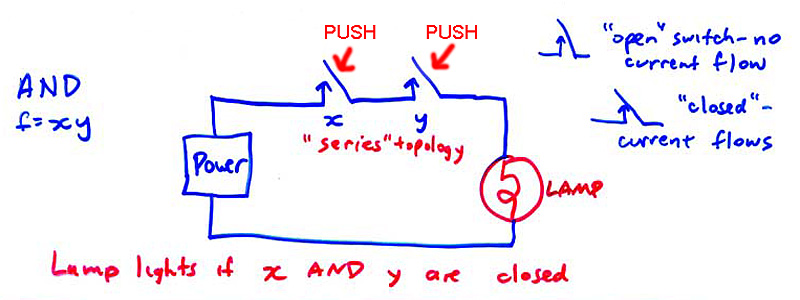
George Boole, a 19th century British logician, was interested in the rapid development of electrical technology, in which telegraphs, motors, and other electromechanical devices were proliferating by the mid 19th century. These devices were controlled by switches. It occurred to him that combinations of switches could simulate various logic functions. So, for example:
Here, current flows and the lamp lights if and only if BOTH switches are closed.
Another possible connection method ("topology") is this:
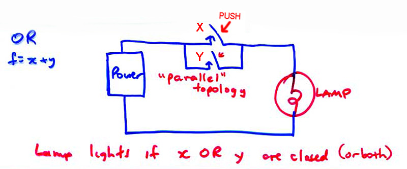
Here, current flows and the lamp lights if EITHER switch is closed, or if both switches are closed.
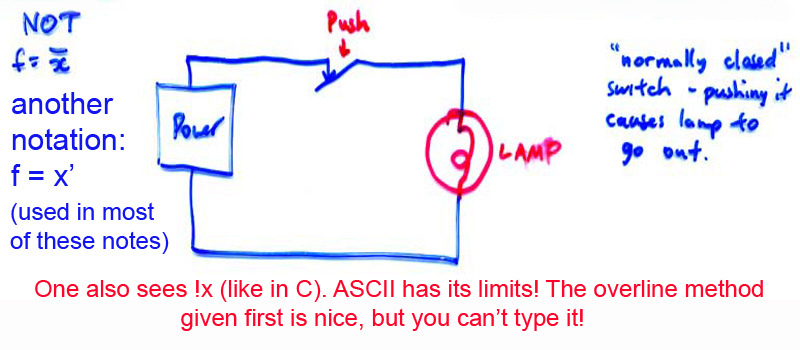
A third basic structure is needed, as it happens:
Boole rather inclusively called his paper that discussed these ideas "The Laws of Thought" as he realized that by combining these operations, any possible logic operation could be performed.
We need a better symbolism than switch drawings. Boole stated his "Boolean algebra" with similarities to ordinary algebra (but some significant differences!) Also, the use of TRUTH TABLES allows a compact representation of "Boolean functions".
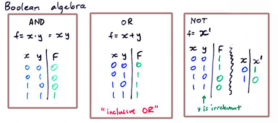
In each of the three cases, which correspond to the switch diagrams above, F (for FUNCTION) is the state of the lamp: 0 = OFF 1 = ON. The X and Y are called INPUT VARIABLES or just INPUTS; 0 means "Don't push the switch" and 1 means "push the switch". For a normal switch, pushing it closes it, so current flows. But, for a normally closed switch, pushing it OPENS it, stopping the flow of current.
While this was an interesting curiosity, showing a perhaps unexpected relationship between electrical technology and mathematical logic, nothing much practical was done with these ideas for many decades.
The switch representations shown above all require human intervention to perform logic. One could combine switches and lamps to cause operations such as addition to be done. This would work by having someone push switches corresponding to the numbers, most conveniently in binary. Lamps would light, cuing the operator to push other switches. This would continue for several steps, until finally the answer would appear on a set of lamps dedicated to that purpose. Naturally, this is so cumbersome as to be practically useless.
The development of the telegraph, and later the telephone switching system, led to the rapid perfection of the electromachanical "RELAY". This is a switch that can be automatically pushed by an outside current, possibly supplied by another relay (hence the term). These can be combined using Boolean techniques, which we will discuss on the next page, to produce an automatic adder, or any other operation, including a complete computer. Such devices, called by M R Williams "The Mechanical Monsters" were built in the 1930s and 1940s. You can learn about these in CPSC 409.
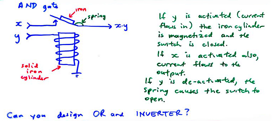
The AND function may be implemented as shown below:
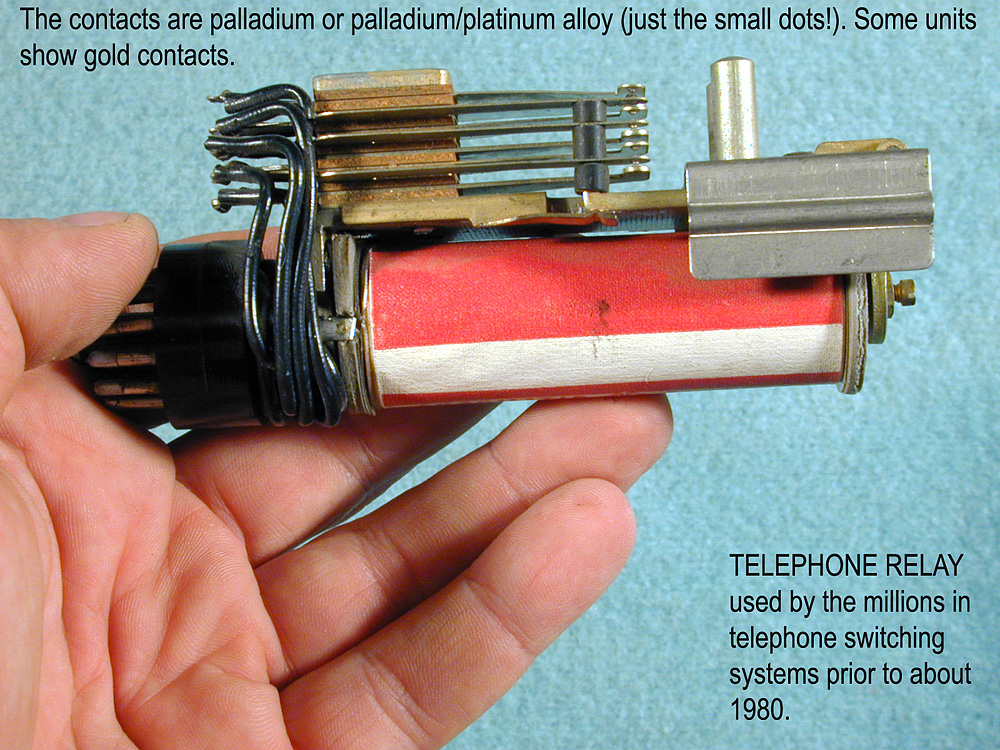
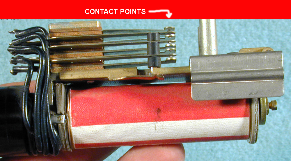
A real relay is shown below:
The next diagram shows the complete set of possible 2 input functions. Of the 16 possible, about 8 are useful and the others are trivial or rather seldom used.
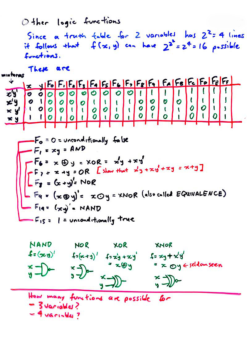
It turns out that one can produce any of the 16 functions by appropriate combinations of NAND. That is, NAND is a "universal gate". As a stunt, one could construct a complete computer out of nothing but NAND gates (F14 above). The NOR is also universal. NAND is preferred today since the physics of silicon semiconductors used in VLSI devices results in NAND being faster than NOR, overall.
(Q)BONUS SKetch and explain the operation of a NAND and NOR gate, using modern CMOS logic.
(Q)Give a brief historical note explaining the original motivation for Boolean algebra.
(Q)Tabulate the 16 2-imput functions of X and Y and identify AND; OR; NOT X; NOT Y; NAND; NOR; XOR; XNOR; X; Y; UNCONDITIONALLY FALSE; UNCONDITIONALLY TRUE.
(Q)How many Boolean functions exist with (a)2 variables, (b)3 variables, (c)4 variables, and (d)5 variables.
MANO2: p29ff, p 56-62
MANO3: p 27ff, p51-7
We will not be testing you on algebraic manipulation of Boolean functions; we don't have time in this course to teach this. You may have done some of it in another course, also. However, we would like you to get a bit of a feeling for this material, so we will discuss graphical methods of simplifying Boolean functions. This is with the Karnaugh map ("K Map").
To start off, we consider an arbitrary 3 variable function (2-imput functions are too easy; we showed the complete list of 16 above). At least 3-input functions allow a "space" of 256 possibilities; we will later also look at 4 input functions, in which there are 65536 ("64K") possibilities.
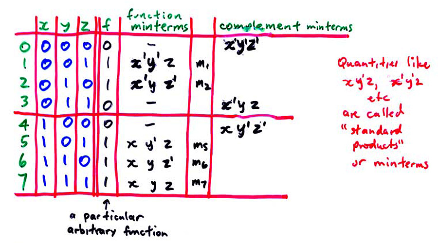
You might wonder where that particular function came from. It is arbitrary; I just made it up. In general, a function arises from some real world problem. Later, we will look at addition; you will see how the addition process can be formulated using a 3 imput truth table similar to the one shown just above.
On the left of the diagram above, we wee in green a list of ordinal numbers 0..7 which correspond to the binary numbers whose bits are the function inputs X, Y and Z. The function is true for numbers 1,2,5,6 and 7, and false for the others. If we look at #1 (XYZ = 001) we can say that the function is true, in this case, when X is 0, Y is 0 AND Z is 1. Algebraically, we can state this fact as X'Y'Z. Since this looks like a "product" or multiplication, in ordinary algebra, it is called a "product" in Boolean algebra. This is too bad in a way, since it can lead to confusion; it looks like a product but is in no way similar, really. Perhaps it would have been better if it had been called an AND TERM or something, but that didn't happen.
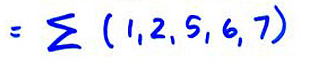
So, we can say that the function is TRUE if X'Y'Z OR X'YZ' OR XY'Z OR XYZ' OR XYZ. More compactly, we can use the "sigma notation" shown below:
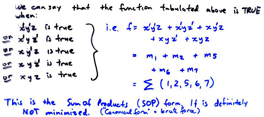
Looking at this function, with its five AND terms ("products") we might wonder if the functionality could be obtained with fewer products.
[For example, the function X'Y'Z' + X'Y'Z + X'YZ' + X'YZ + XY'Z' + XY'Z + XYZ' + XYZ is a very simple one: it is equal to 1 (i.e. UNCONDITIONALLY TRUE!) ]
(Q)BONUS Show algebraically that the above 8 minterms reduce to 1.
A simplification argument is shown in the diagram below:
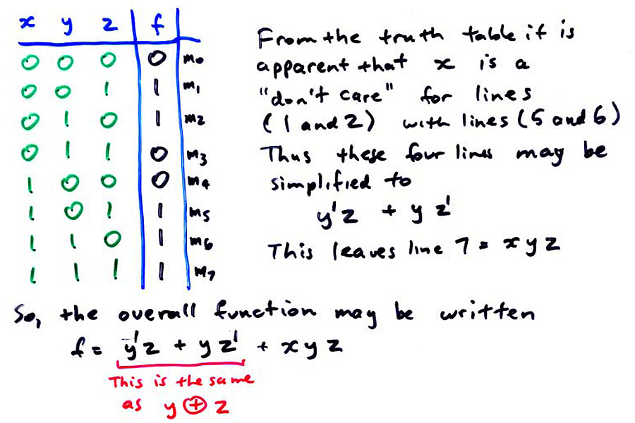
The argument is a bit tricky. For lines 1 and 2, the function is true, and YZ are 01 and 10, respectively. For lines 5 and 6, the function is also true, and YZ are 01 and 10, respectively. That is, if YZ are 01 or 10, regardless of the state of X, the function is true. Thus, for these four lines, X can be dropped, as its value doesn't matter. Refer to the diagram.
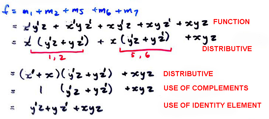
We would like a simplification method that is less "tricky". Algebra is possible but there is no general algorithm that is guaranteed to give a simplest result. The diagram below shows an algebraic method. You are not required to do this for exam purposes.
The result of these simplifications is often referred to as the "Sum of Products" or SOP form. The K map will give us the SOP form. There is also a POS form, derivable from the K map, which I will not discuss here. It is discussed in the 321 pages.
MANO2: p49-55
MANO3: p44-51
We start with the introduction below:

These simplifications can be spotted on the truth table or obtained algebraically, but these methods (especially the algebraic method) seem unconvincing at guaranteeing minimization. [The astute student might note that the ordinal difference in (a) is 4 and (b) is 1. It turns out that this simplification process always involves ordinal differences that are a power of 2.] (Q) BONUS Give an argument based on truth tables and Boolean algebra that supports this idea.
We see that the conventional sequential listing of the truth table obscures the simplifications possible. A K map is a truth table drawn in such a way that the simplifications are immediately apparent. The K map method can be programmed; this is called the Quine-McCluskey algorithm.
The basic principle is to list the truth table ordinality in a reflected code sequence. Instead of going 000, 001, 011, 010 etc we list the numbers so as to change only one bit at a time, e.g. 000, 001, 011, 010, etc. There are many possible reflected code sequences; I chose the one in which we always try to change the rightmost possible bit. (Q) Fill in the last four terms. ANS 110, 111, 101, 100, then repeats 000 etc. This particular code is called the "Gray code".
(Q) Give the four bit gray code sequence (16 steps in the cycle).
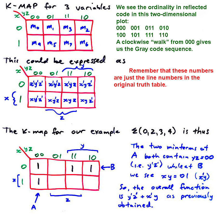
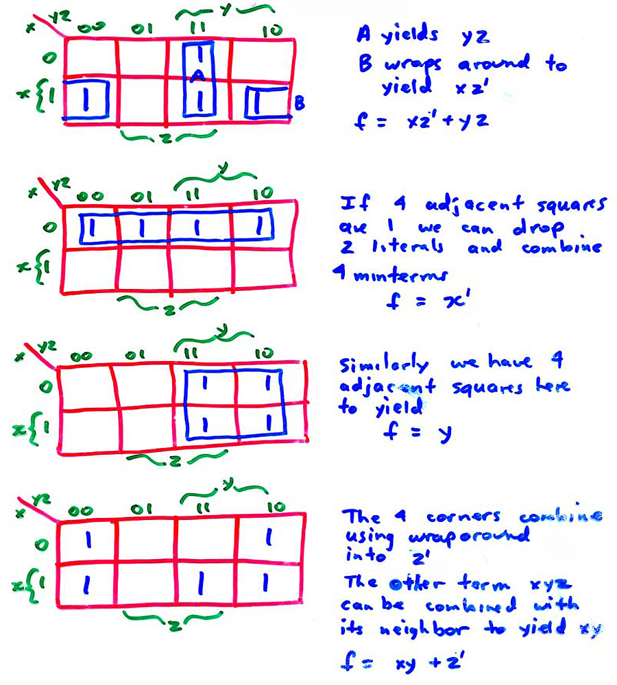
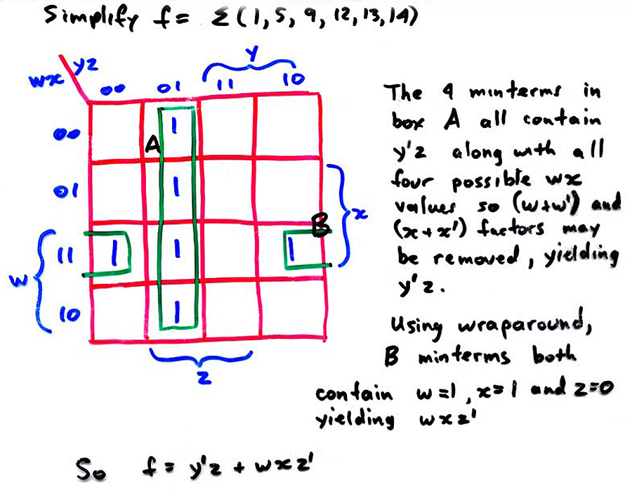
BASIC RULE: obtain groups of 2 or 4 (or 8 or 16 for larger K maps) of adjacent cells and keep what is common to all cells in the group. In A above, y'z' is common to both cells. A grouping of 2 cells allows for removal of one variable letter (x in this case). (The letter is sometimes called a "literal".) Thus, grouping four cells in a line or a square allows removal of two literals.
Here are some more examples:
(Q)Use the K map to simplify the first example shown several diagrams above:
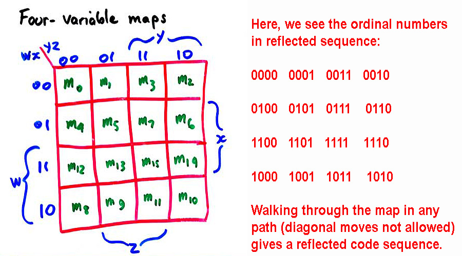
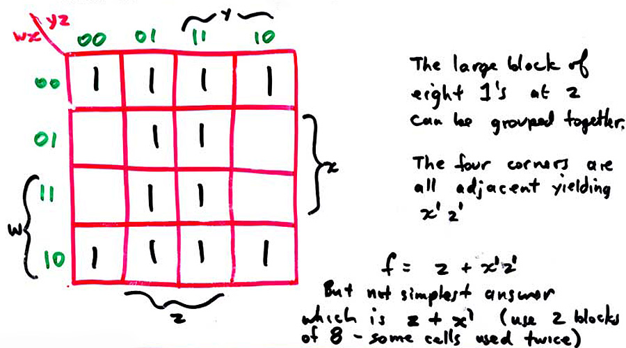
We can go to a four-variable map as shown:
Here is an example:
Another example:
Maps may be drawn for larger numbers of input variables, but we need more dimensions. A 5 variable map can be drawn as two four variable maps stacked vertically; a 6 variable map will use four 4-variable maps stacked vertically in order 00, 01, 11, 10. Beyond 6 variables, we need four or more dimensions; this is too hard for me.
The Quine-McCluskey algorithm will work with any number of variables; it looks for ordinality differences of 2^n and groups the terms. If two pairs of such terms differ by 2^n, a further grouping is possible; this corresponds to the K map grouping of 4 cells.
(Q) BONUS Give an account of the Quine-McCluskey algorithm.
Some of the above results suggest that one could further simplify by grouping variables ("factoring"). Sometimes this is worthwhile, sometimes not. It depends on the actual technology used. (For some technologies, the basic unminimized SOP form is used, as in field programmable gate arrays (FPGAs) which may implement functions directly as stored truth tables! However, for the fastest, smallest circuits, minimization is done.
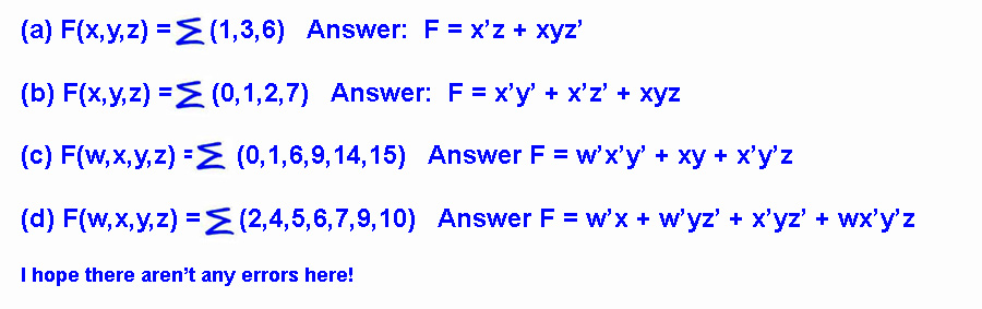
(Q) Simplify the following using K maps:
(Q)Be able to simplify K maps of 3 and 4 variables. There are more examples of K maps on the later pages, especially on 04 Sequential Logic systems: Finite state machines
MANO2: p72-80
MANO3: p64-72
Why do we wish to do the above simplifications? The simpler function will require the least hardware to implement it, and will usually (but not always, due to technical issues) be the fastest, and use the least power.
As mentioned in the introduction, the idea of logic gates arose from study of switch and control circuits. The use of relays allows automatic control, and thus computation.
Relays take tens of milliseconds to change state (i.e. from "open" to "closed" or 0 to 1). Thomas Edison (of light bulb fame) just missed discovering the electronic vacuum tube. He actually built them, as modified light bulbs, in an attempt to discover ways of making the bulbs last longer. However, he was focussed on the electric lamp, and the current he measured flowing in the vacuum didn't suggest any possibilities to him. Many years later, this "Edison effect" was studied, and was discovered to allow an "electronic valve" which could turn off or on in tens of microseconds, or about three orders of magnitude faster than the relay. This is the same speed ratio as that between crawling slowly, and flying on a jetliner! The vacuum tube, of course, was initially used for radio sets, in the 1920s.
Thus, "electronic computers" or "giant electronic brains" became possible by the 1940s. World War 2 delayed things; on the Allied side, most of the best electronic researchers were working on communications and radar, or involved with the atomic bomb. On the German side, Hitler evidently didn't really understand the value of computation (this is a problem with having a country run by an all-powerful dictator at a time of rapid technological change).
[I can't resist mentioning the German Konrad Zuse, now a virtually forgotten pioneer. He understood a great deal about the benefit of using binary computers. In the late 1930s he built some computers in his parents' house in his spare time, using metal strip logic gates, with essentially no support from the Nazi government. His ideas had to be rediscovered independently by American and British engineers and mathematicians later. (Zuse survived the war; his latest computer of the time was destroyed in an air raid, but he rebuilt it and eventually built up a great company, Zuse AG, which was eventually absorbed by Siemens, the giant German electronic conglomerate. He lived into his 90s. See below for his first computer, the Z1, built with metal strips, driven by a motor:
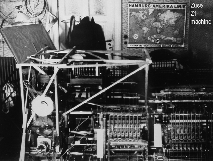
I have an AVI movie of a Zuse Z1 computer replica operating. It appears to have an effective clock speed of about 4Hz, and occupies a space equal to a large tabletop. I will try to find a link to it. It is fascinating to see the metal strips move as it runs a program. The program was stored on 35mm movie film with holes punched in it; Zuse could get discarded movie film readily, and it was quite strong.
Some pictures of Zuse; he is a really fascinating fellow. Too bad he was effectively out of sight during the first years of electronic computer development! After the war, he was "de-briefed" by the Americans, who didn't really know what to make of him. American machines were still using base 10, e.g. the ENIAC; the modern type of binary computer architecture had to wait a couple more years. Zuse could have probably saved the Americans some time. Due to his isolation, we must say that Zuse was not really important in the actual history of the computer, unfortunately.
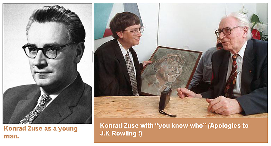
In the second image, Zuse is presenting His Windowsness with a portrait-Zuse also was an artist; in early life he wanted to become an architect.]
Transistors, which allowed an electronic valve action without the need of a vacuum, high voltages, or a fragile glass envelopes, existed by 1950. However, almost 10 years elapsed before transistors became manufacturable in large quantities with good control of parameters. Almost at once, the obvious possibility of depositing multiple transistors on one substrate (the "integrated circuit") was pursued, and by 1970 ICs containing gates were common. Logic systems (see next page) then became integrable on a single module (MSI), then later (by the early 1970s) complete simple CPUs, with steady increases in speed and complexity.
(Q)BONUS Explain how a transistor switch works. You can use either the bippolar junction transistor, or the MOSFET as the basis for your answer.
(Q)List four technologies historically used for computers, and give a couple of brief remarks about each.